
In this simulation, you will build some simple circuits with gates and then use multiple copies of those circuits to build a larger, more complicated device.

You will need one 7486, two 7408’s and two 7432’s to build the above circuit.
#2 BIT HALF ADDER TRUTH TABLE FULL#
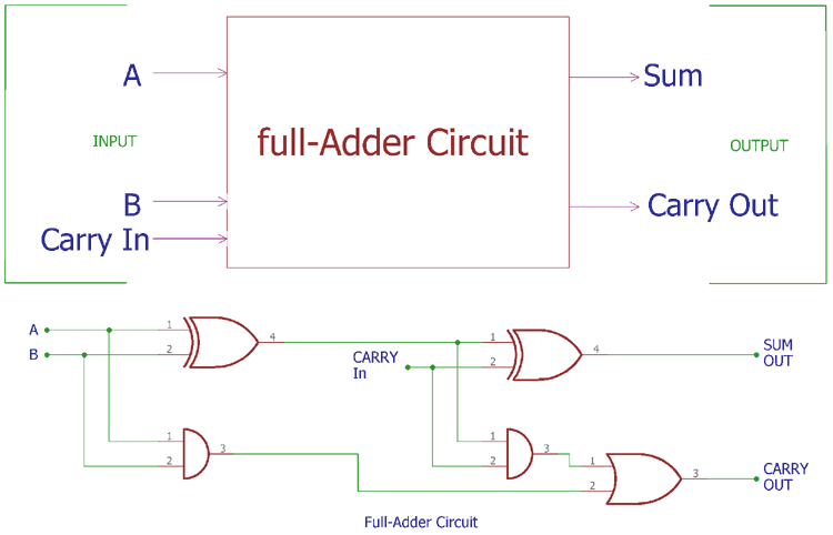
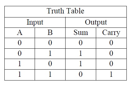
Thus, to add two 8 bit numbers, 8 full address is needed that can be formed by cascading two of the 4-bit blocks. In block diagram form, the 2-bit Full Adder looks like: Figure 4. In a computer, for a multi-bit operation, each bit must be represented by a full adder and must be added simultaneously. With the help of this type of symbol, one can add two bits together, taking a carry from the next lower order of magnitude and sending a carry to the next higher order of magnitude. The schematic representation of a single bit Full Adder is shown below: The Full adder circuit diagram is shown below: Thus, C OUT will be an OR function of the half adder CARRY outputs. If any of the half adder logic produces a carry, there will be an output carry. The second half adder logic can be used to add C IN to the sum produced by the first half adder circuit. The first half adder circuit will be used to add A and B to produce a partial sum. Thus, a full adder circuit can be implemented with the help of two half adder circuits. The C OUT will be true only if any of the two inputs out of the three are HIGH or at logic 1. The output S is an EX-OR between the input A and the half-adder SUM output B. The truth table of the Full Adder Circuit is shown below. The output carry is designated as C OUT, and the normal output is designated as S. The two inputs are A and B, and the third input is a carry input C IN. The main difference between a half adder and a full adder is that the full-adder has three inputs and two outputs. The full adder is a little more difficult to implement than a half adder.


 0 kommentar(er)
